Steel Connection Design: Real Failures & Fixes Engineers Miss
Real-world steel connection failures, panel zone mistakes, bolt pretension errors, timber-steel fixes, and BIM coordination tips no textbook covers.
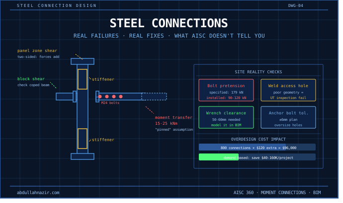
Steel Connection Design Nobody Talks About: Real Failures, Real Fixes, and What AISC Tells You vs What Actually Happens on Site
Every structural engineer learns connection design from textbooks and codes. AISC 360, moment connections, shear tabs, end plates — you can calculate them in your sleep. But here's what nobody teaches you: the gap between a connection that passes code check and a connection that actually works in the real world is enormous.
I've reviewed hundreds of steel connections across commercial, industrial, and infrastructure projects. The failures I've seen were never because someone got the bolt shear capacity wrong. They happened because of things your professor never mentioned and your code never explicitly covers.
This post is everything I wish someone had told me early in my career.
The Dirty Secret of "Pinned" Connections
Every junior engineer models a shear tab or clip angle as a perfect pin. Zero moment transfer. Clean and simple in your ETABS model. The reality? Every single "pinned" connection transfers some moment. Always. The question is whether you've accounted for it.
A standard shear tab with 3 bolts on a W460 beam transfers roughly 15-25 kNm of moment under typical loading — even when designed as a simple shear connection. That moment goes straight into the column web or flange. On a heavily loaded column already working at 80% capacity, that unaccounted moment matters.
What to do about it: For any column carrying more than 70% of its axial capacity, add a quick hand check of the moment your "pinned" connections are realistically introducing. It takes 10 minutes and has saved me from some very awkward conversations with fabricators mid-construction.
Bolt Pretension: The Assumption That Kills Connections
You design a slip-critical connection. You specify Class A faying surface, pretensioned bolts, the works. Your calculation shows the connection handles the load with a 1.4 safety factor. Beautiful. Now the bolts arrive on site and the ironworkers use an impact wrench, stop when it feels tight, and move on.
This is not an exaggeration. It happens on every project where inspection isn't rigorous. An M24 A325 bolt specified at 179 kN pretension might be installed at 90-120 kN if the turn-of-nut method isn't enforced or if bolt threads are dirty. Your slip-critical connection just became a bearing connection by accident.
Practical fix: For anything genuinely slip-critical (crane girders, connections subject to fatigue, seismic moment frames), get it in the spec that direct tension indicators (DTIs) or twist-off bolts are required. These are self-verifying — the DTI gaps close at the correct pretension and twist-off bolts shear off their spline when pretension is achieved. Costs maybe $2-3 more per bolt. Worth every cent.
Column Web Crippling — The Failure Mode Everyone Skips
You check bolt shear. You check weld capacity. You check beam moment capacity. You even check panel zone shear. Do you check column web crippling and web local yielding under the concentrated force from a beam flange in a moment connection? Most engineers don't — not routinely.
Column web local yielding at the tension flange of a moment connection is calculated as follows: the design strength is φR_n = φ × (5k + N) × F_yw × t_w, where k = distance from outer face of flange to web toe of fillet, N = bearing length (beam flange width), F_yw = web yield stress, and t_w = web thickness. For a W250x89 column receiving a W460x82 beam in a moment connection, this check frequently controls — especially on columns with thin webs.
When it doesn't work, your options are continuity plates (stiffeners between flanges at the beam level) or a doubler plate on the web. Continuity plates are more common and typically cheaper to fabricate. But here's the part fabricators hate: continuity plates in a W-shape with a k-zone restriction need to be fitted and welded carefully to avoid the heat-affected zone issue. Get your weld procedure right or you'll have cracking at the k-zone.
Rule of thumb: If your beam flange force (M / (d_beam - t_fb)) exceeds 60% of the column web local yielding resistance, add continuity plates. Don't wait for the calculation to technically fail. The extra 40% buffer accounts for real-world load combinations and construction tolerances.
Weld Sizing: What the Code Allows vs What You Should Actually Specify
AISC lets you use the directional strength increase for fillet welds loaded at an angle. A weld loaded perpendicular to its axis is 1.5× stronger than one loaded parallel. So technically you can use smaller welds on end plate connections where the force is predominantly transverse. Technically correct. Practically, I'd urge caution.
Here's why: on site, welders don't always achieve consistent weld profiles. A 6mm fillet weld that relies on the 1.5× directional factor has effectively the same load path capacity as a 9mm weld loaded in shear — but only if the weld geometry is perfect. An undersized weld leg, a convex profile, or poor fusion at the root eliminates that advantage entirely.
My actual practice: I use the directional factor in calculations to satisfy the code check, but I specify weld sizes one step above the minimum (e.g., 8mm instead of 6mm) on moment connection flanges. The fabrication cost difference is negligible. The confidence margin is significant. No project manager has ever complained that a weld was too good.
Timber-Steel Hybrid Connections: Where Projects Go Wrong
Mass timber construction is growing fast. CLT floors on steel frames, glulam beams sitting on steel columns, timber-steel hybrid systems everywhere. And the connection between timber and steel is where most of the problems live.
Problem 1 — Moisture movement nobody accounts for: Glulam and CLT move. Across the grain, dimensional changes of 0.5-1.0% per 1% change in moisture content are realistic. A 200mm deep glulam beam can move 2-4mm seasonally. If your steel hanger or ledger angle doesn't accommodate this movement, you're splitting timber or bending steel over time. Use slotted holes in the direction of grain movement. Always. Even if the calculation technically works without them.
Problem 2 — Splitting at notched ends: Notching a glulam beam end to sit on a steel ledger is common. It's also a reliable way to create a tension-perpendicular-to-grain failure if the geometry isn't right. The notch creates a stress concentration that the beam calculation completely misses. Per NDS, the reduced section shear capacity at a notch on the tension face is V_r = (2/3) × F_v × b × (d_n / d)² × d_n, where d_n is the notch depth. A notch of just 20% of beam depth on the tension face reduces shear capacity by 36%. Engineers routinely underestimate this.
Problem 3 — Galvanic corrosion between steel and timber connectors: Treated timber (ACQ, CA treated) is highly corrosive to standard zinc-plated hardware. On any exposed or semi-exposed timber-steel connection using treated lumber, specify hot-dip galvanized or stainless steel hardware. The additional cost is $40-80 per connection. The cost of replacing corroded connectors in a 5-year-old structure is orders of magnitude more.
The Panel Zone Problem in Steel Moment Frames
Panel zone shear is one of those checks that feels academic until you work on a building with heavy moment frames and relatively light columns. Then it becomes very real, very fast.
The panel zone is the column web area bounded by the beam flanges at a moment connection. It resists shear from the unbalanced beam moments. The AISC check for panel zone shear strength is φR_v = φ × 0.6 × F_y × d_c × t_w × (1 + 3b_cf × t_cf² / (d_b × d_c × t_w)), where d_c = column depth, t_w = column web thickness, b_cf = column flange width, t_cf = column flange thickness, and d_b = beam depth.
What catches engineers out: in a two-sided moment connection (beams framing into both column flanges), the panel zone sees additive shear from both beams. If moments are of the same sign (as in a gravity frame with balanced loading), they partially cancel. In a seismic frame under lateral load, the moments are opposite — they add. The panel zone shear can be 40-60% higher than a one-sided connection calculation would suggest.
Doubler plates vs thicker columns: When the panel zone fails the check, the instinct is to add a doubler plate. But on heavier column sections, specifying a column one size up is often cheaper than the fabrication cost of fitting and welding a doubler plate. Get a quote from your fabricator before automatically going to doubler plates. On three recent projects, a column upgrade saved $8,000-15,000 in fabrication cost over doubler plates.
BIM for Steel: What the Model Misses That Kills the Erection Schedule
This section is specifically for those using Tekla Structures, Revit Structure, or any BIM platform for steel detailing. The model looks perfect on screen. Then steel arrives on site and erection slows to a crawl. Here's why.
Erection clearance for bolt installation: Your BIM model shows bolts in their final position. It does not show the wrench clearance needed to install them. A standard impact wrench needs roughly 50-60mm clearance around the bolt head. If your beam web is 8mm from a column flange and you've specified M20 bolts in a shear tab, the ironworker physically cannot get a wrench in there. Model the wrench envelope. Tekla has a clearance check tool. Use it on every connection in a confined space before issuing fabrication drawings.
Erection sequence and temporary stability: A steel frame during erection is not the frame your analysis model assumes. Individual columns and beams before full connection is achieved are vulnerable to buckling and overturning that your final-state model never sees. For frames taller than 4 stories or with long unbraced bays, include an erection engineering note specifying minimum temporary bracing requirements. This protects you legally and protects the ironworkers physically.
Anchor bolt projection tolerances: Anchor bolts cast in concrete have a tolerance of ±6mm in plan and ±13mm in elevation per AISC Code of Standard Practice. Your base plate holes need to accommodate this. A base plate designed with holes just 2mm larger than the bolt diameter will need to be redrilled on site when the bolts aren't exactly where the drawing says. Standard practice is oversized holes (bolt diameter + 6-10mm) with a leveling nut or shim stack. Model it this way and detail it explicitly — don't leave it to the fabricator to figure out.
Steel Deck and Composite Slab: The Coordination Problem
Composite steel deck slabs are everywhere. They're efficient, fast to construct, and well understood structurally. The coordination with MEP is where time and money disappear.
Penetrations through composite slabs for mechanical, electrical, and plumbing need to be located and sized before the deck is poured — not after. Post-pour core drilling through composite slabs with shear studs is expensive, risks cutting studs (which compromises your composite action), and creates re-inspection requirements. But on most projects, MEP coordination isn't complete when structural drawings are issued.
What actually works: In your BIM coordination workflow, create a freeze date for MEP penetration locations that is 3 weeks before deck pour. Any penetrations not confirmed by that date get a reserved zone — an area where shear studs are omitted and the deck is designed as non-composite locally. After pour, MEP cuts their penetrations in the reserved zone with no structural consequence. This adds maybe 2% to your steel tonnage for the non-composite zones. It saves weeks of RFI delays and re-inspection.
The Real Cost of Overdesigning Steel Connections
There's a culture in structural engineering of designing connections conservatively. Use more bolts than you need. Weld the full length. Add stiffeners when in doubt. It feels responsible. On a single connection it costs $50-200 extra. Across a 10,000m² steel-framed building with 800 connections, overdesigned connections add $40,000-160,000 to the fabrication cost — and weeks to the fabrication schedule because more work per connection means slower throughput at the shop.
I'm not suggesting under-designing. I'm suggesting right-sizing. Run the actual calculation. Use the actual loads from your analysis, not the maximum beam capacity. The AISC design guide approach of designing connections for the maximum beam strength makes sense for seismic design and moment frames. For ordinary gravity connections in a non-seismic zone, it massively overdestimates the required capacity. A W360x57 beam at 60% capacity does not need a connection designed for 100% of the beam's plastic moment.
The conversation to have with your client: "I can design these connections two ways — conservative maximum-strength design, or demand-based design using actual loads. The difference is approximately $X in fabrication cost and Y weeks in schedule. Both approaches meet code. Which would you prefer?" Most clients, when given the choice and the numbers, choose demand-based. Let them make that call with full information.
Thermal Movement in Long Steel Structures
Steel expands at 12 × 10⁻⁶ per °C. A 100m long steel building in a climate with 50°C seasonal temperature range expands and contracts 60mm end to end. That's 60mm of movement that has to go somewhere.
Expansion joints are the standard answer. But the location and detailing of expansion joints in steel-framed buildings is surprisingly poorly handled on many projects. Common mistakes include placing the joint at mid-length of the building (correct) but then connecting roof cladding continuously across the joint (wrong — the cladding buckles or tears), or providing the joint in the structure but not in the concrete slab on grade (the slab cracks predictably at the joint location because it's the weakest point).
Checklist for thermal movement in long steel buildings:
- Expansion joint spacing: maximum 60-70m in most climates, 45m in extreme temperature zones
- All cladding, roofing, and slab systems must have independent joints aligned with the structural joint
- Slotted connections (not fixed) on one side of each expansion joint in the structural frame
- Document which end of slotted connections is the "fixed" end — erectors frequently install backwards
- At roof level, provide a drip flashing detail at the expansion joint that allows 80mm movement — significantly more than the calculated movement, because installations are never perfectly centered
What I Actually Check Before Signing Off on Steel Drawings
After years of reviewing steel fabrication drawings and witnessing what actually causes problems during construction, here is my personal checklist — the things the code doesn't tell you to check but experience absolutely does.
Connection checks beyond code: Column web local yielding and crippling at moment connections, panel zone shear in two-sided connections, prying action on bolts in tension (T-stub and end plate connections — the code check is easy to miss), block shear on coped beams (frequently the controlling failure mode, frequently skipped), and weld access hole geometry on fully welded moment connections (poor access hole geometry causes weld defects that don't show up until UT inspection fails the weld).
Fabrication and erection practicality: Wrench clearance on all bolt groups, minimum edge distances actually achievable given the plate geometry, whether the specified weld size is achievable in the joint geometry (a 10mm fillet weld in a tight inside corner is not the same as a 10mm fillet in open air), and whether the erection sequence requires any temporary works not shown on drawings.
BIM coordination: Structural model clash-free against MEP and architectural models at connection zones, base plate and anchor bolt details coordinated with civil foundation drawings, and steel camber annotations consistent with composite slab ponding calculations.
Steel design done well is a craft. The code gives you the rules. Experience gives you the judgment to know when the rules are insufficient, when to go further, and when to push back on design decisions that look fine on paper but will cause problems in the field.
If this post saved you one RFI, one site visit to investigate a failed connection, or one awkward call with a contractor — it did its job.
.webp)
Abdullah Nazir
Structural Engineer & BIM Specialist — CEO of Defteng Pvt. Ltd.
Writes from real project work across Pakistan, the US, New Zealand, Australia and Belgium — structural design, BIM coordination, and the software that automates the repetitive parts of both.